This special function allows reading of CS (Component Security) from DCM6.2 on bench.
Obtaining the Component Security bytes will help you in the following situations
-
Engine Control Unit replacement
-
Key Programming (All Keys Lost situation)
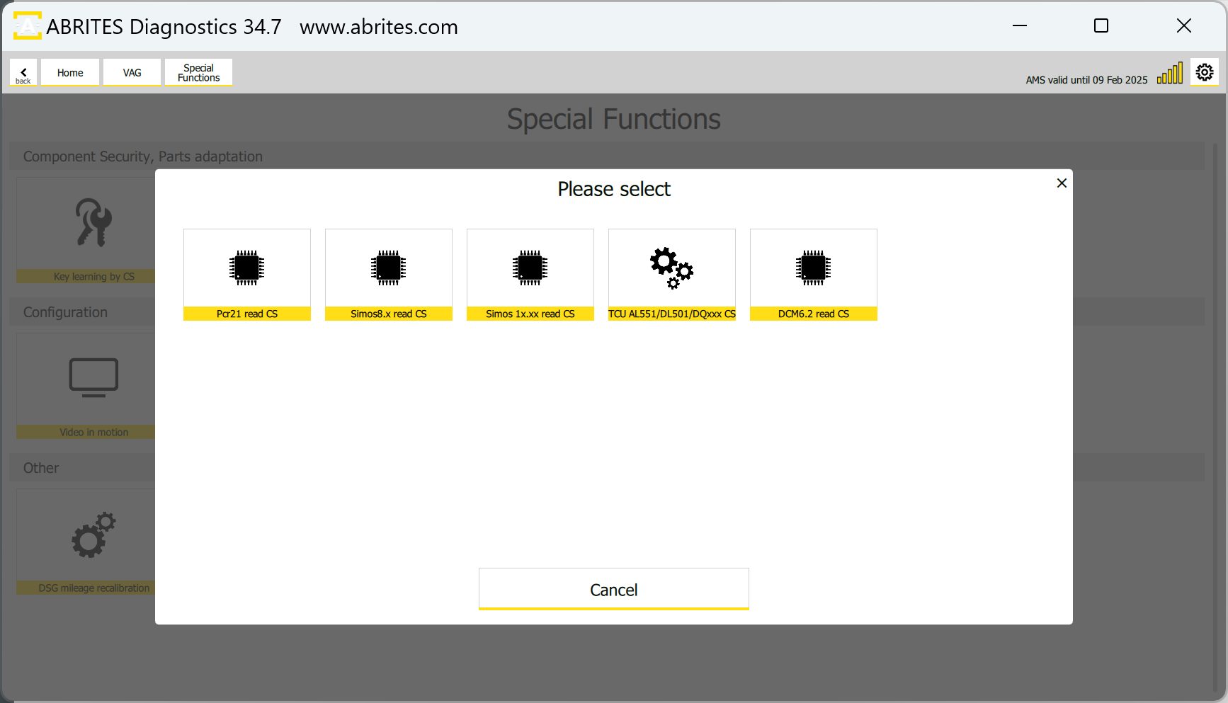
Most of the vehicles equipped with DCM6.2 engine control units use a manual transmission and blade keys. Considering this, obtaining of the Component Security (CS) and reading the Instrument cluster by using the ZN085 may help in All Keys Lost situation. The procedure is executed through the VAG Online > “Special Functions” > “Read CS on bench” menu and click on “DCM6.2 Read CS”.
Connections
Below you may find the required connections for reading the DCM6.2 ECU
Important: ZN151 DS Box should be version 2.4! Versions 2.2 and 2.3 would not working for this procedure.
There are 3 ways you can perform the connection.
- Connection using CB403 (CB401) cable and ZN151 DS Box:
The white wire coming from the CB403 (CB401) cable should be bridged as there are 2 boot pins and only one boot wire at this cable set.
Connector T60
-
PIN 52 – Boot (White Wire)
-
PIN 41 – Boot (White Wire)
Connector Т94
-
PIN 2 – GND (Black Wire)
-
PIN 6 – 12V+ (Yellow Wire)
-
PIN 67 – CAN L (Blue Wire)
-
PIN 68 – CAN H (Red Wire)
-
PIN 75 – T1 (Brown Wire)
-
PIN 87 – IGN (Orange Wire)
- Connection using CB403 cable and ZN151 DS Box:
Connector T60
-
52pin – Boot (white wire)
-
41pin – Boot (white wire)
Connector Т94
-
6pin – B+ (Yellow)
-
2pin – GND (black)
-
87pin – IGN (orange)
-
68pin – CAN H (red)
-
67pin – CAN L (blue)
-
75pin – T1 (brown)
- CB032 - DCM6.2 Connection Cable
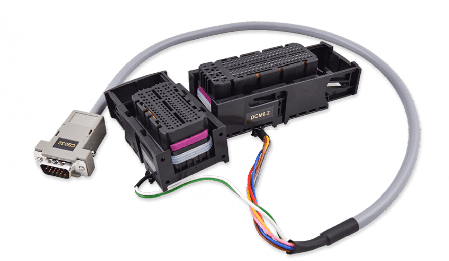
CB032 - DCM6.2 Connection Cable - This cable is used for connection with DCM6.2 Engine Control Units in VAG vehicles. CB032 connects the ZN151 ABRITES Distribution Box when reading Component Security Data (CS) on Bench for VAG ECU DELPHI DCM6.2.
The DB15 connector of the CB032 is connected to the corresponding slot of the ZN151.
On the other side of the CN032 there are 2 dedicated connectors that go into the ECU’s connectors.
HD15 pinout
-
1 - pink - IGN T94 pin 87
-
2 - yellow - B+ T94 pin 6
-
5 - white and green - BOOT 1 T60 pin 52
-
7 - brown - T1 T94 pin 75
-
8 - red - CAN H T94 pin 68
-
11 - grey - GND T94 pin 2
-
14 - blue - CAN L T94 pin67
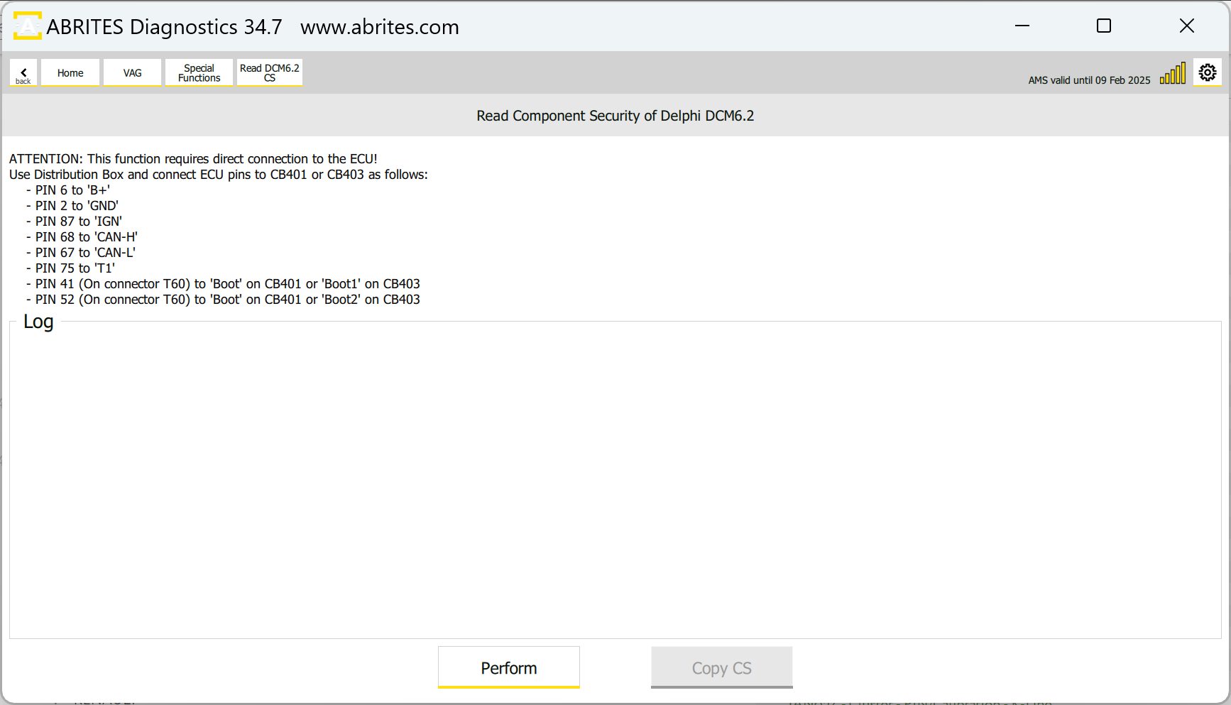
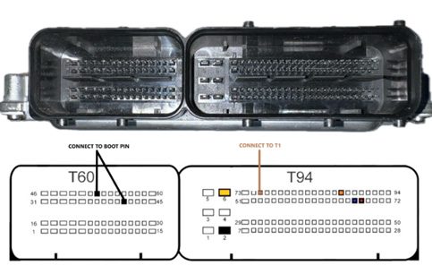
Below you may find picture from the software, with guidelines for the connection and the PIN OUT connection diagram of the DCM6.2. Once all connections are made, please press the “Perform” button to execute the procedure, it may take up to 5 minutes, once done the CS will be displayed.