When working on bench, you need to connect to the pins of the BCM unit, using the additional cable for bench work from the KP002 set as follwos:
-
Connect the OBD connectior of the cable to the OBD connector of the device
-
Connect the 2 wires (CAN) coming out of the device into the extendor cables that would allow connection to the pins.
-
Connect all pins to the BCM unit
-
Power up the whole set ( ZN063 power adapter can be used)
Bench Connector Legend
-
Male OBDII Port
-
Black power cable with a socker (can be used with ZN076)
-
Yellow wire (with a split) - 12V+
-
Black - GND
-
Blue - CAN H
-
Red - CAN L
-
additionally, the 2 wires coming out of device are also Red for CAN H and Blue for CAN L and are used to connect to the RFA CAN pin connectors.
Once everything is connected properly the procedure goes as follows
-
Power up the whole set
-
At this point the LED indicator will blick in orange 1 time and it will start fast green light blicking. If all the connections are alright, the LED indicator will start blicking in green slowly, meaning the device is now in operation.
-
At the end of the procedure, the device should have solid green light on the LED indicator.
-
Now the vehicle’s alarm is deactivated and it is ready for the key programming procedure.
*Procedure may take uo to 72 hours
KP002 bench connections
- L8B2 BCM
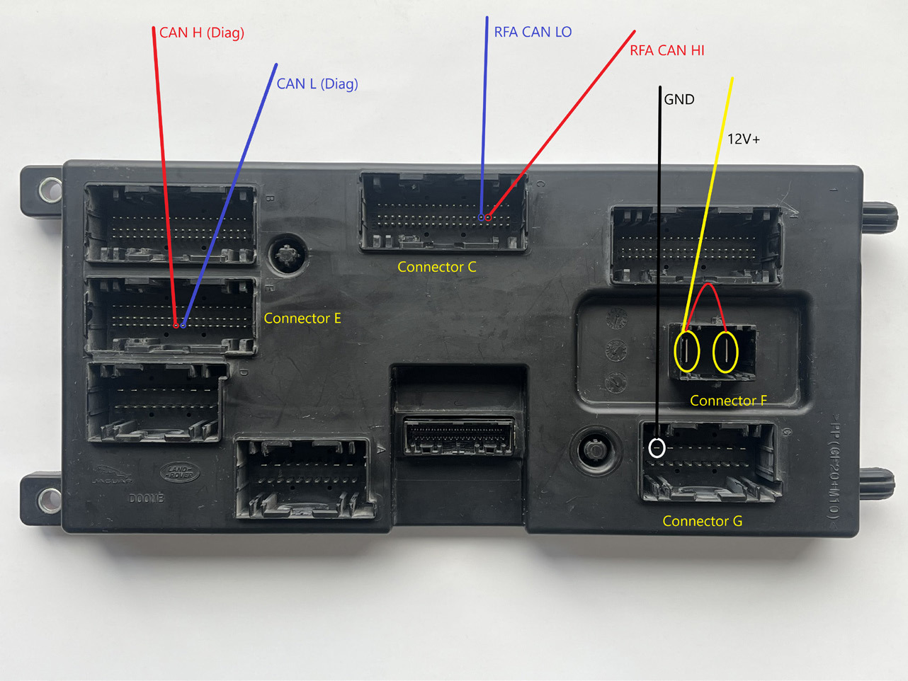
Legend
Connector F
-
PIN 2 - 12V+
-
PIN 1 - additional 12V+ cabl
Connector G
PIN 1 - GND
Connector C: RFA CAN
PIN 36 - CAN L - Blue Wire (comming out of the device)
PIN 37 - CAN H - Red Wire (comming out of the device)
Connector E: Diag CAN
PIN 51 - CAN L - Blue Wire
PIN 50 - CAN H - Red Wire
- JPLA BCM
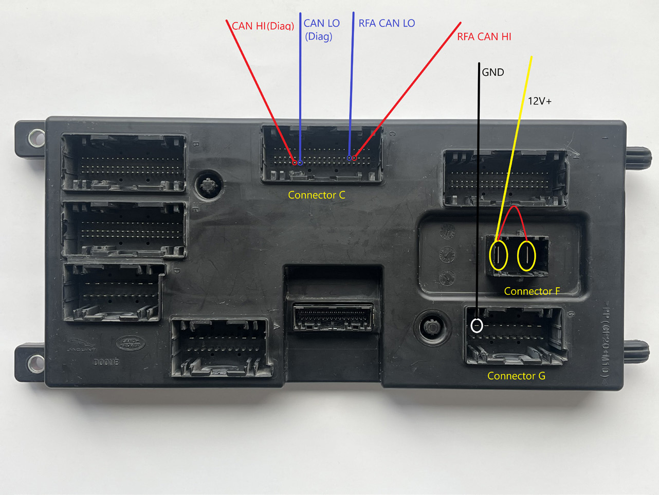
Legend
Connector F
-
PIN 2 - 12V+
-
PIN 1 - additional 12V+ cable
Connector G
PIN 1 - GND
Connector C: RFA CAN
PIN 36 - CAN L - Blue Wire (comming out of the device)
PIN 37 - CAN H - Red Wire (comming out of the device)
PIN 50 - CAN H - Red Wire
PIN 51 - CAN L - Blue Wire Legend
Below you can see an example of a L8B2 BCM connected on bench.
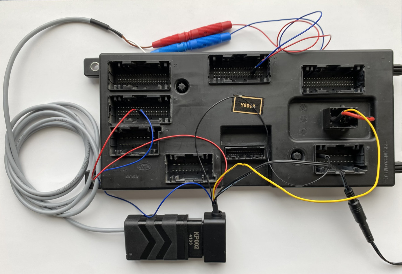
Operation of the device
There is a LED indicator on the device, which provides information of the state of the device/procedur:
-
Fast Green blinking - testing the connections
-
Alternating Green and Red blinking - wrong connection of the CAN wires.
-
Slow Green blinking - work in progress
-
Solid Green light - process finished
-
Solid Red light - does not operate - this would most probably mean you have not made the correct connections