Using the ZN086 you can read unlocked MC9S12's from the xExxx series - PFlash, DFlash and EEPROM data, save them, and later write to another module. The whole procedure takes minutes and allows you to adapt these modules in the vehicle (clone the donor module onto the new/used one).
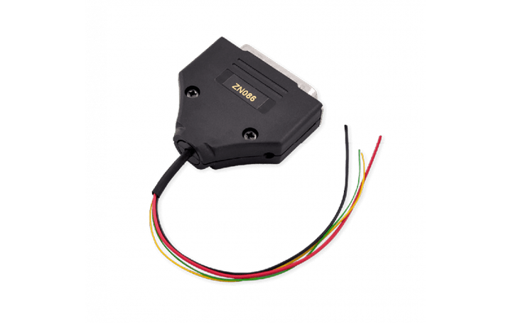
MC9S12 processor is used in a variety of modules, such as DSM and ISM in FBS4 Mercedes-Benz vehicles, etc.
Required equipment
- Abrites AVDI interface
- ZN130 ABPROG programmer
- ZN086 - MC9S12 adapter for ABPROG
- Soldering equipment, and the means to lift one processor pin
- The processor's data sheet, to identify the pin
Step-by-step procedure
1. Find the pin that needs lifting
Important: The PIN that needs lifting is specific for each processor, and you need to find that information first. Since there are many variations, you will need to do your own research and get to the processor's data sheet. The PIN that needs lifting is the “RST” or reset PIN.
2. Solder the adapter
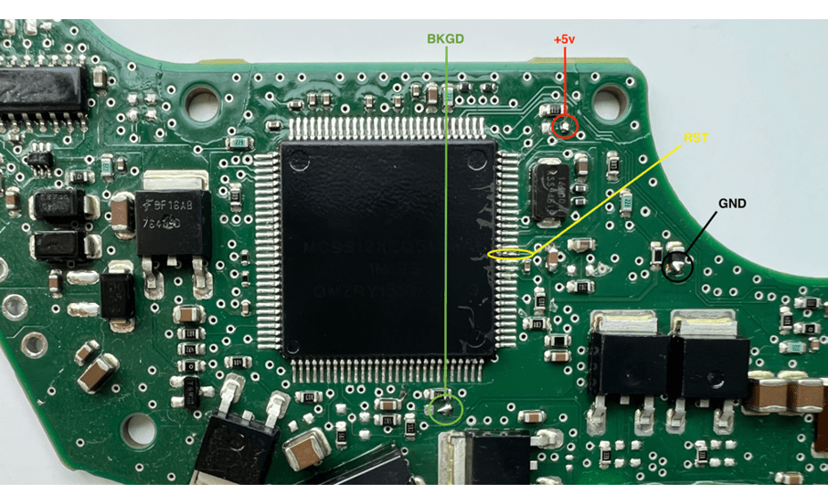
The ZN086 adapter is soldered onto four points on the PCB (one of which is the lifted pin). The four DB25 connections are GND (pin 14), +5v (pin 21), RST (pin 11) and BKGD (pin 19) - see DB25 Male Connector.
3. Connect the chain
The ZN086 is connected to the ABPROG; the ABPROG is connected to AVDI, and AVDI to your laptop.
4. Start the software
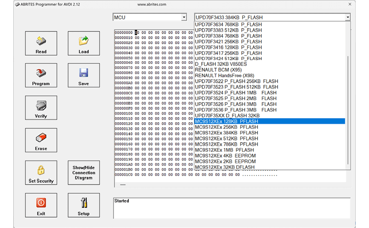
ABPROG upgraded software is used, but the procedure can also be done with the Classic one. From the main screen you need to click “MCU” and find the options.
5. Read, save, write
First, you need to read PFlash and EEPROM, save them, and then program them on the replacement module's PCB.
Important notes
- Only unlocked MC9S12s from the xExxx series can be read this way.
- The lifted pin is the “RST”/reset pin, and which physical pin that is differs per processor - look it up in the data sheet before touching the board.
- For more details on how the ZN086 is used, please check the following video.
Troubleshooting
| Issue | Likely cause | Solution |
|---|---|---|
| No communication with the MCU | The RST pin is not actually lifted, or a solder point is wrong | Re-check the data sheet pin and all four solder points |
| The clone does not work in the car | PFlash or EEPROM was not written to the replacement | Read and save both, then write both to the replacement PCB |