Special tools and workshop equipment required
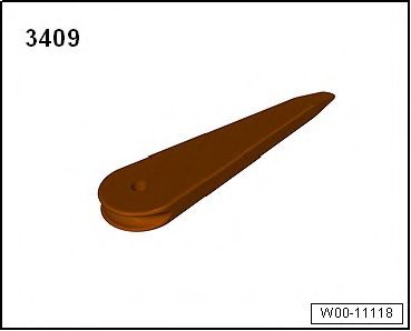
Removal wedge -3409-
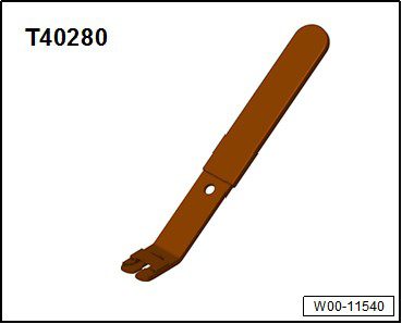
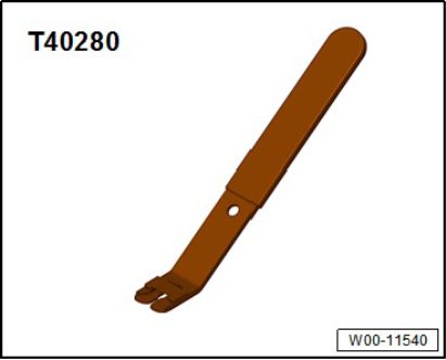
Removal tool -T40280-
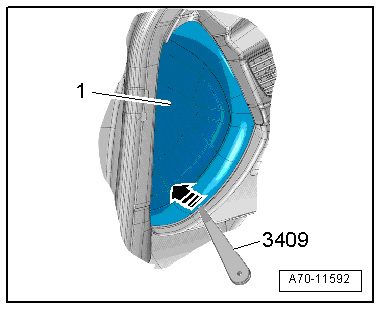
- Remove dash panel cover (side)
1.1 Prise off dash panel cover (side) -1- using removal wedge -3409--arrow- and detach.
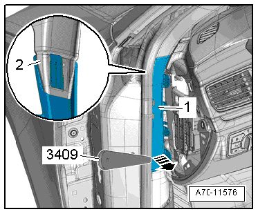
1.2 Unclip trim cover -1- for A-pillar (bottom) using removal wedge -3409--arrow- and detach downwards from A-pillar trim (top) -2-.
- Remove B-pillar trim (top)
2.1. Move belt height adjuster to lowest possible position.
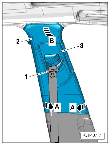
2.2. Apply removal wedge -3409- at bottom edge of B-pillar trim (top) and unclip Bpillar trim (top) -2--arrows A-.
2.3. Equipment version with vent: Unplug electrical connector for vent.
2.4. Pull B-pillar trim (top) out of mounting on body -arrow B-; to do so, swivel trim inwards and at the same time pull it off downwards.
2.5. Thread belt -1- with latch plate through slide for belt height adjuster -3- and detach B-pillar trim.
- Remove B-pillar trim (bottom)
Special tools and workshop equipment required
Removal lever 80-200 Removal tool T40280
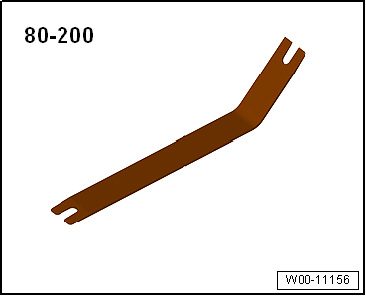
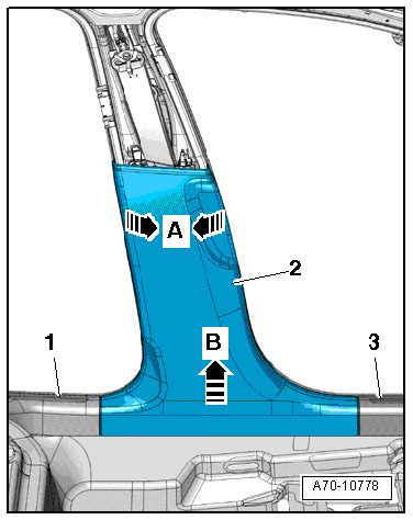
3.1. Starting at top, use removal lever -80 - 200- to unclip B-pillar trim (bottom) -2- from B-pillar arrows A-.
3.2. Unclip B-pillar trim (bottom) from side member -arrow B- in area of sill panel trims (rear -1- and front -3-).
4.Remove dash panel cover (driver side)
Special tools and workshop equipment required
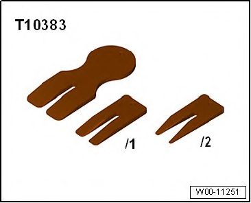
Wedges T10383
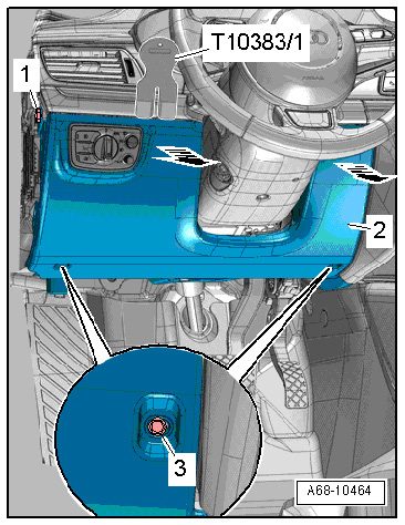
4.1 Remove bolt -1- at side.
4.2 Remove bolts -3- at bottom.
4.4 Unclip top edge of dash panel cover (driver side) -2- from dash panel -arrows- using wedge -T10383/1-.
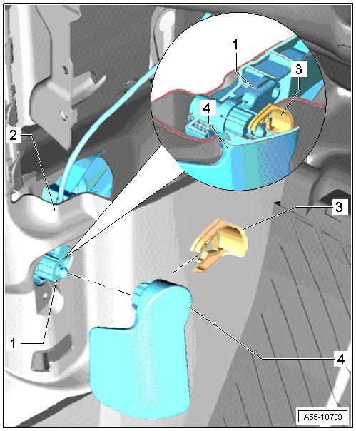
5.Remove operating lever for bonnet
5.1.Lever retaining clip out of operating lever.
5.2.Detach cover from operating lever at side.
6.Remove sill panel trim (front).
6.1 Remove bolt -1- for sill panel trim (front).
6.2Starting at rear, use removal wedge -3409- to unclip sill panel trim (front) -2- from side member and pull off towards rear -arrows-.
6.3 Detach sill panel trim (front).
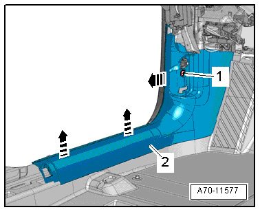
So after all this is made, you have access to the following connectors
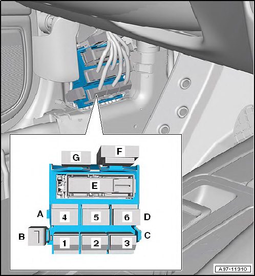
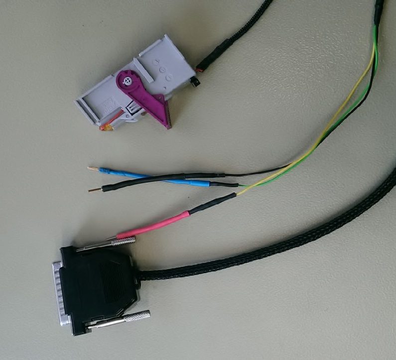
So you can prepare following cable to connect the AVDI to the car
Here is the PIN-out:
t46a/12L - connected to PIN15 of the DB25 of the AVDI (CAN-H)
t46a/12H - connected to PIN7 of the DB25 of the AVDI (CAN-L)
t17h/8 (cable is violet/black) and the connector is red (position 2 on A97-11310 picture) – connected to the PIN8 of the DB25 of the AVDI (K-Line)
You need to connect also 12V and GND to the DB25.